FDTD Mesh
From openEMS
Contents |
General
The mesh used by the finite-difference time-domain (FDTD) method is a strictly rectilinear mesh using Yee-cells.
For detailed informations you should have a close look here: FDTD
Rules of thumb
Here are some (maybe) helpful rules of thumb:
- The largest mesh cell must not be bigger than about a tenth of the smallest wavelength.
Better: max(Δx,y,z) < λmin / 15
The smallest wavelength is defined by the greatest excited frequency and the material properties!
- Make the mesh as coarse as possible and as fine as needed
- Keep an adequate distance to an absorbing boundary
Try to keep structure > λmax / 4 from a PML
- Create a smooth mesh: Neighboring cell sizes should not exceed a factor of ~2
- Thirds Rule : At the edges of a 2D metal you have a strong electric field enhancement that FDTD has trouble to calculate properly.
That means that e.g. for micro-strip line (MSL) the line-impedance and wave propagation differs somewhat between simulation and measurement. So, it is preferred in precision calculation to put a mesh line 1/3 inside and 2/3 outside the metal.
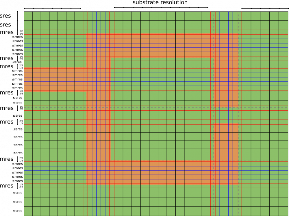
FDTD Mesh example
- The first thing is to place the thirds rule mesh lines 1/3 inside and 2/3 outside the metal (the red ones).
- In second, place the metal mesh lines (the blue ones) which should cover all Micro Strip Lines in the width direction with a maximum spacing of mres (mres is metal mesh resolution < = λmin / 20 for example)
- A the end, complete this mesh with substrate mesh lines (the black ones) which should cover all the substrate with a maximum spacing of sres (sres is substrate mesh resolution < = λmin / 10 for example)
Mesh lines are calculation time so try to add only needed lines (sometimes, red or blue lines already cover the substrate mesh)
openEMS example
- Define a homogeneous mesh with the matlab interface:
SmoothMeshLines enables us to define meshes with points which match important dimensions and have an interval less than a specified maximum. This is demonstrated with the following simple examples.
First, a simple mesh from 1 to 10 with a maximum resolution of 1:
>> SmoothMeshLines([1 10], 1)
ans =

    1    2    3    4    5    6    7    8    9   10
Now suppose we want a point at 5.2. This is added to the vector (first argument):
>> SmoothMeshLines([1 5.2 10], 1)
ans =

 Columns 1 through 8:

    1.0000    1.8400    2.6800    3.5200    4.3600    5.2000    6.1600    7.1200

 Columns 9 through 11:

    8.0800    9.0400   10.0000
Create a homogeneous mesh with a resolution of 10mm in x- and y-direction and 15mm in z-direction:
CSX = InitCSX();
mesh.x = 0:10:500;
mesh.y = SmoothMeshLines([0 750], 10);
mesh.z = SmoothMeshLines([0 2000], 15);
CSX = DefineRectGrid(CSX, 1e-3 ,mesh); % define the mesh with a drawing unit of 1mm (1e-3)
FDTD cylindrical mesh [1]
An adaption of the conventional FDTD algorithm to the cylindrical coordinate has been realized with only minimal changes. As in the rectilinear mesh, the Maxwell equations are evaluated on the surfaces and edges of cylindrical Yee cell but with different formulation in the calculation of surface area and edge lengths.
To reduce inevitable smaller cell size as r approaches 0 which induces smaller step size and hence slower simulation, a new multi-grid approach for cylindrical mesh is introduced. In contrast to conventional FDTD multi-grid that increases the mesh resolution, this method is adopted for reducing excessive mesh resolution in the center and its neighboring area. By introducing sub-grid, every second radial lines of the original mesh is excluded. This enlarge the relevant cell size and time step by a factor of two. For a huge number of mesh line in azimuthal direction, this approach can be nested several times. Correspond to it, the cell size and time step are increased by a factor of 2n where n is the number of nested stage.
example
Cylindrical mesh without subgrid:
FDTD = InitFDTD( 1e9, 1e-3, 'CoordSystem' , 1 );
CSX = InitCSX('CoordSystem' , 1);
mesh.r= AutoSmoothMeshLines([0 200], 10);
mesh.a= 0:2*pi/352:2*pi;  % azimuthal equidistant
mesh.z= AutoSmoothMeshLines([-1000 1000], 15);
CSX = DefineRectGrid( CSX, 1e-3, mesh ); % define the mesh with a drawing unit of 1mm (1e-3)
Cylindrical mesh with subgrid defined at r = 50mm :
FDTD = InitFDTD( 1e9, 1e-3, 'CoordSystem' , 1 ,'MultiGrid',50);
CSX = InitCSX('CoordSystem' , 1);
mesh.r= AutoSmoothMeshLines([0 200], 10);
mesh.a= 0:2*pi/352:2*pi;  % azimuthal equidistant
mesh.z= AutoSmoothMeshLines([-1000 1000], 15);
CSX = DefineRectGrid( CSX, 1e-3, mesh ); % define the mesh with a drawing unit of 1mm (1e-3)
Boundary Conditions
To complete the mesh, boundary conditions must be specified. This is done with the function SetBoundaryCond in this manner:
BC = [xmin xmax ymin ymax zmin zmax];
FDTD = SetBoundaryCond(FDTD, BC, varargin)
where values for the BC vector are:
   0 = PEC      or  'PEC'
   1 = PMC      or  'PMC'
   2 = MUR-ABC  or  'MUR'
   3 = PML-ABC  or  'PML_x' with pml size x => 4..50
Here are two equivalent examples:
BC = [ 1     1     0     0     2     3     ]  %using numbers or
BC = {'PMC' 'PMC' 'PEC' 'PEC' 'MUR' 'PML_8'}  %using equivalent strings

