Tutorial: CRLH Parameter Extraction
From openEMS
- Download the latest matlab files using Github: CRLH_Extraction.m & CreateCRLH.m
- Simulation Time: ~ 3 min
We will cover in this tutorial:
- setup a feeding mircostrip line & port
- apply an inhomogeneous mesh used for improved accuracy and simulation speed
- use an external script to setup a CRLH unit cell
- use the port voltages and currents to extract the unit cell equivalent circuit parameter
Contents |
First Steps
- Install and verify your openEMS installation: Tutorial: First Steps
- You may have a look at the tutorial introducing a MSL: Tutorial: Microstrip Notch Filter
Matlab Simulation Script
- Start the script within an empty environment:
close all
clear
clc
- Setup the simulation & geometrical parameter
physical_constants;
unit = 1e-6; % specify everything in um

feed_length = 30000;

substrate_thickness = [1524 101 254];
substrate_epsr = [3.48 3.48 3.48];

CRLH.LL = 14e3;     %CRLH totel (line) length
CRLH.LW = 4e3;      %CRLH unit cell width (without the stubs)
CRLH.GLB = 1950;    %CRLH gap width bottom layer
CRLH.GLT = 4700;    %CRLH gap width top layer
CRLH.SL = 7800;     %CRLH stub length (bottom layer, both sides)
CRLH.SW = 1000;     %CRLH stub width  (bottom layer, both sides)
CRLH.VR = 250;      %CRLH via hole radius (stub -> ground)
CRLH.TopSig = sum(substrate_thickness);  %top layer height
CRLH.BottomSig = CRLH.TopSig - substrate_thickness(end);  %bottom layer height

% frequency range of interest
f_start = 0.8e9;
f_stop  = 6e9;
- Setup the FDTD parameter including the excitation time signal and boundary conditions
FDTD = InitFDTD('NrTs', 20000 );
FDTD = SetGaussExcite( FDTD, (f_start+f_stop)/2, (f_stop-f_start)/2 );
BC   = {'PML_8' 'PML_8' 'MUR' 'MUR' 'PEC' 'PML_8'};
FDTD = SetBoundaryCond( FDTD, BC );
- Setup the inhomogeneous FDTD mesh and the CRLH unit cell
CSX = InitCSX();
resolution = c0/(f_stop*sqrt(max(substrate_epsr)))/unit /30; % resolution of lambda/30

mesh.x = [-feed_length-CRLH.LL/2 0 feed_length+CRLH.LL/2];
mesh.y = [-30000 0 30000];
substratelines = cumsum(substrate_thickness);
mesh.z = [0 cumsum(substrate_thickness) linspace(substratelines(end-1),substratelines(end),4) 20000];

% create the CRLH unit cell (will define additional fixed mesh lines)
[CSX mesh] = CreateCRLH(CSX, mesh, CRLH, resolution/4);

% Smooth the given mesh
mesh.x = SmoothMeshLines(mesh.x, resolution, 1.5, 0);
mesh.y = SmoothMeshLines(mesh.y, resolution, 1.5, 0);
mesh.z = SmoothMeshLines(mesh.z, resolution, 1.5, 0);
CSX = DefineRectGrid( CSX, unit, mesh );
- A closer look inside the CreateCRLH function:
This function will add all the necessary metal objects composing a CRLH unit cell. Additionally it will add appropriate mesh lines as needed for a smooth mesh including a thin metal handling.
function [CSX mesh] = CreateCRLH(CSX, mesh, CRLH, resolution, translate)

if (nargin<5)
    translate = [0 0 0];
end

CSX = AddMetal(CSX, 'metal_top');
one_two_third = [-resolution/3 2*resolution/3];

start = [-CRLH.LL/2 -CRLH.LW/2 CRLH.TopSig]+translate;
stop  = [-CRLH.GLT/2  CRLH.LW/2 CRLH.TopSig]+translate;
CSX = AddBox(CSX, 'metal_top', 10, start, stop);
mesh.x = [mesh.x start(1) stop(1)+one_two_third];
mesh.y = [mesh.y start(2)-one_two_third stop(2)+one_two_third];

start = [+CRLH.LL/2  -CRLH.LW/2 CRLH.TopSig]+translate;
stop  = [+CRLH.GLT/2  CRLH.LW/2 CRLH.TopSig]+translate;
CSX = AddBox(CSX, 'metal_top', 10, start, stop);
mesh.x = [mesh.x start(1) stop(1)-one_two_third];

CSX = AddMetal(CSX, 'metal_bot');
start = [-(CRLH.LL-CRLH.GLB)/2 -CRLH.LW/2 CRLH.BottomSig]+translate;
stop  = [+(CRLH.LL-CRLH.GLB)/2  CRLH.LW/2 CRLH.BottomSig]+translate;
CSX = AddBox(CSX, 'metal_bot', 10, start, stop);
mesh.x = [mesh.x start(1)-one_two_third stop(1)+one_two_third];

start = [-CRLH.SW/2 -CRLH.LW/2-CRLH.SL CRLH.BottomSig]+translate;
stop  = [+CRLH.SW/2  CRLH.LW/2+CRLH.SL CRLH.BottomSig]+translate;
CSX = AddBox(CSX, 'metal_bot', 10, start, stop);
mesh.x = [mesh.x start(1)-one_two_third stop(1)+one_two_third];
mesh.y = [mesh.y start(2) stop(2)];

CSX = AddMetal(CSX, 'via');
start = [0 -CRLH.LW/2-CRLH.SL+CRLH.SW/2 0]+translate;
stop  = [0 -CRLH.LW/2-CRLH.SL+CRLH.SW/2 CRLH.BottomSig]+translate;
CSX = AddCylinder(CSX, 'via', 10, start, stop, CRLH.VR);
mesh.x = [mesh.x start(1)+[-1 0 1]*CRLH.VR];
mesh.y = [mesh.y start(2)+[-1 0 1]*CRLH.VR];

start(2) = -start(2);
stop(2)  = -stop(2);
CSX = AddCylinder(CSX, 'via', 10, start, stop, CRLH.VR);
mesh.y = [mesh.y start(2)+[-1 0 1]*CRLH.VR];
end
- Add the subtrate layer:
substratelines = [0 substratelines];
for n=1:numel(substrate_thickness)
    CSX = AddMaterial( CSX, ['substrate' int2str(n)] );
    CSX = SetMaterialProperty( CSX, ['substrate' int2str(n)], 'Epsilon', substrate_epsr(n) );
    start = [mesh.x(1),   mesh.y(1),   substratelines(n)];
    stop  = [mesh.x(end), mesh.y(end), substratelines(n+1)];
    CSX = AddBox( CSX, ['substrate' int2str(n)], 0, start, stop );
end
- Add the two feeding MSL ports
CSX = AddMetal( CSX, 'PEC' );
portstart = [ mesh.x(1) , -CRLH.LW/2, substratelines(end)];
portstop  = [ -CRLH.LL/2,  CRLH.LW/2, 0];
[CSX,port{1}] = AddMSLPort( CSX, 999, 1, 'PEC', portstart, portstop, 0, [0 0 -1], 'ExcitePort', 'excite', 'FeedShift', 10*resolution(1), 'MeasPlaneShift',  feed_length/2);

portstart = [ mesh.x(end) , -CRLH.LW/2, substratelines(end)];
portstop  = [ +CRLH.LL/2,   CRLH.LW/2, 0];
[CSX,port{2}] = AddMSLPort( CSX, 999, 2, 'PEC', portstart, portstop, 0, [0 0 -1], 'MeasPlaneShift',  feed_length/2 );
- Create the simulation folder/ write the xml file/ View the file using AppCSXCAD and run openEMS
Sim_Path = 'tmp';
Sim_CSX = 'CRLH.xml';

[status, message, messageid] = rmdir( Sim_Path, 's' ); % clear previous directory
[status, message, messageid] = mkdir( Sim_Path ); % create empty simulation folder

WriteOpenEMS( [Sim_Path '/' Sim_CSX], FDTD, CSX );
CSXGeomPlot( [Sim_Path '/' Sim_CSX] );
RunOpenEMS( Sim_Path, Sim_CSX );
Post-Processing
- Read the port voltages & currents and calculate the port characteristics
close all
f = linspace( f_start, f_stop, 1601 );
port = calcPort( port{1}, Sim_Path, f, 'RefPlaneShift', feed_length*unit);

s11 = port{1}.uf.ref./ port{1}.uf.inc;
s21 = port{2}.uf.ref./ port{1}.uf.inc;

plot(f/1e9,20*log10(abs(s11)),'k-','LineWidth',2);
hold on;
grid on;
plot(f/1e9,20*log10(abs(s21)),'r--','LineWidth',2);
l = legend('S_{11}','S_{21}','Location','Best');
set(l,'FontSize',12);
ylabel('S-Parameter (dB)','FontSize',12);
xlabel('frequency (GHz) \rightarrow','FontSize',12);
ylim([-40 2]);
- Extract the unit cell parameter:
You may have a look at this paper [1] on CRLH parameter extraction details.
A = ((1+s11).*(1-s11) + s21.*s21)./(2*s21);
C = ((1-s11).*(1-s11) - s21.*s21)./(2*s21) ./ port{1}.ZL;

Y = C;
Z = 2*(A-1)./C;

iZ = imag(Z);
iY = imag(Y);

fse = interp1(iZ,f,0);
fsh = interp1(iY,f,0);

df = f(2)-f(1);
fse_idx = find(f>fse,1);
fsh_idx = find(f>fsh,1);

LR = 0.5*(iZ(fse_idx)-iZ(fse_idx-1))./(2*pi*df);
CL = 1/(2*pi*fse)^2/LR;

CR = 0.5*(iY(fsh_idx)-iY(fsh_idx-1))./(2*pi*df);
LL = 1/(2*pi*fsh)^2/CR;

disp([' Series tank: CL = ' num2str(CL*1e12,3) 'pF;  LR = ' num2str(LR*1e9,3) 'nH -> f_se = ' num2str(fse*1e-9,3) 'GHz ']);
disp([' Shunt  tank: CR = ' num2str(CR*1e12,3) 'pF;  LL = ' num2str(LL*1e9,3) 'nH -> f_sh = ' num2str(fsh*1e-9,3) 'GHz ']);
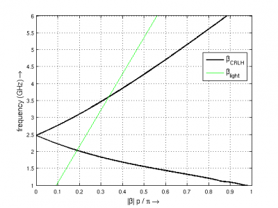
- Calculate and display the dispersion diagram:
figure
beta = -angle(s21)/CRLH.LL/unit;
plot(abs(beta)*CRLH.LL*unit/pi,f*1e-9,'k-','LineWidth',2)
grid on;
hold on;
plot(2*pi*f./c0*CRLH.LL*unit/pi,f*1e-9,'g-')
ylim([1 6])
xlabel('|\beta| p / \pi \rightarrow','FontSize',12)
ylabel('frequency (GHz) \rightarrow','FontSize',12)
l = legend('\beta_{CRLH}','\beta_{light}','Location','Best');
set(l,'FontSize',12);


