Tutorial: Simple Patch Antenna
From openEMS
- Download the latest matlab file using Github: Simple_Patch_Antenna.m
- Simulation Time: < 1 min
We will cover in this tutorial:
- setup patch, substrate and ground
- setup a lumped feeding port
- adding a near-field to far-field (nf2ff) box
- calculate the S-Parameter of the antenna
- calculate and plot the far-field pattern
Contents |
First Steps
- Install and verify your openEMS installation: Tutorial: First Steps
Matlab Simulation Script
- Start the script within an empty environment:
close all
clear
clc
- Setup the physical constants and antenna parameters
physical_constants;
unit = 1e-3; % all length in mm

% patch width in x-direction
patch.width  = 30; % resonant length
% patch length in y-direction
patch.length = 40;

%substrate setup
substrate.epsR   = 3.38;
substrate.kappa  = 1e-3 * 2*pi*2.45e9 * EPS0*substrate.epsR;
substrate.width  = 60;
substrate.length = 60;
substrate.thickness = 1.524;
substrate.cells = 4;

%setup feeding
feed.pos = -5.5; %feeding position in x-direction
feed.width = 2;  %feeding port width
feed.R = 50;     %feed resistance

% size of the simulation box
SimBox = [200 200 100];
- Setup FDTD parameters, excitation signals & boundary conditions
f0 = 2e9; % center frequency
fc = 1e9; % 20 dB corner frequency
FDTD = InitFDTD('NrTS', 30000 );
FDTD = SetGaussExcite( FDTD, f0, fc );
BC = {'MUR' 'MUR' 'MUR' 'MUR' 'MUR' 'MUR'}; % boundary conditions
FDTD = SetBoundaryCond( FDTD, BC );
- Setup the CSXCAD mesh
max_res = c0 / (f0+fc) / unit / 20; % cell size: lambda/20
CSX = InitCSX();

%create fixed lines for the simulation box, substrate and port
mesh.x = [-SimBox(1)/2 SimBox(1)/2 -substrate.width/2 substrate.width/2 -patch.width/2 patch.width/2 feed.pos];
mesh.x = SmoothMeshLines( mesh.x, max_res, 1.4); % create a smooth mesh between specified fixed mesh lines

mesh.y = [-SimBox(2)/2 SimBox(2)/2 -substrate.length/2 substrate.length/2 -feed.width/2 feed.width/2 -patch.length/2 patch.length/2];
mesh.y = SmoothMeshLines( mesh.y, max_res, 1.4 );

%create fixed lines for the simulation box and given number of lines inside the substrate
mesh.z = [-SimBox(3)/2 linspace(0,substrate.thickness,substrate.cells) SimBox(3)/2 ];
mesh.z = SmoothMeshLines( mesh.z, max_res, 1.4 );

CSX = DefineRectGrid( CSX, unit, mesh );
- Setup the geometry
%% create patch
CSX = AddMetal( CSX, 'patch' ); % create a perfect electric conductor (PEC)
start = [-patch.width/2 -patch.length/2 substrate.thickness];
stop  = [ patch.width/2  patch.length/2 substrate.thickness];
CSX = AddBox(CSX,'patch',10,start,stop); % add a box-primitive to the metal property 'patch'

%% create substrate
CSX = AddMaterial( CSX, 'substrate' );
CSX = SetMaterialProperty( CSX, 'substrate', 'Epsilon', substrate.epsR, 'Kappa', substrate.kappa );
start = [-substrate.width/2 -substrate.length/2 0];
stop  = [ substrate.width/2  substrate.length/2 substrate.thickness];
CSX = AddBox( CSX, 'substrate', 0, start, stop );

%% create ground (same size as substrate)
CSX = AddMetal( CSX, 'gnd' ); % create a perfect electric conductor (PEC)
start(3)=0;
stop(3) =0;
CSX = AddBox(CSX,'gnd',10,start,stop);
- Setup the feeding port as a lumped port with 50 Ohms
start = [feed.pos-.1 -feed.width/2 0];
stop  = [feed.pos+.1 +feed.width/2 substrate.thickness];
[CSX port] = AddLumpedPort(CSX, 5 ,1 ,feed.R, start, stop, [0 0 1], true);
- Add a nf2ff box
SimBox = SimBox - max_res * 4; %reduced SimBox size for nf2ff box
[CSX nf2ff] = CreateNF2FFBox(CSX, 'nf2ff', -SimBox/2, SimBox/2);
- Create simulation folder
- Write xml simulation file
- Visualize the Geometry using AppCSXCAD
- Run openEMS
%% prepare simulation folder
Sim_Path = 'tmp';
Sim_CSX = 'patch_ant.xml';

[status, message, messageid] = rmdir( Sim_Path, 's' ); % clear previous directory
[status, message, messageid] = mkdir( Sim_Path ); % create empty simulation folder

%% write openEMS compatible xml-file
WriteOpenEMS( [Sim_Path '/' Sim_CSX], FDTD, CSX );

%% show the structure
CSXGeomPlot( [Sim_Path '/' Sim_CSX] );

%% run openEMS
RunOpenEMS( Sim_Path, Sim_CSX );
Post-Processing
- Read in port voltages and currents
%% postprocessing & do the plots
freq = linspace( max([1e9,f0-fc]), f0+fc, 501 );
port = calcPort(port, Sim_Path, freq);
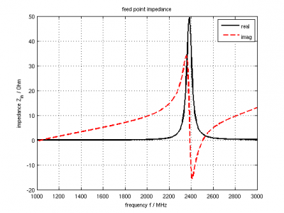
- Calculate & plot antenna input-impedance
Zin = port.uf.tot ./ port.if.tot;
s11 = port.uf.ref ./ port.uf.inc;
P_in = 0.5 * port.uf.inc .* conj( port.if.inc ); % antenna feed power

% plot feed point impedance
figure
plot( freq/1e6, real(Zin), 'k-', 'Linewidth', 2 );
hold on
grid on
plot( freq/1e6, imag(Zin), 'r--', 'Linewidth', 2 );
title( 'feed point impedance' );
xlabel( 'frequency f / MHz' );
ylabel( 'impedance Z_{in} / Ohm' );
legend( 'real', 'imag' );
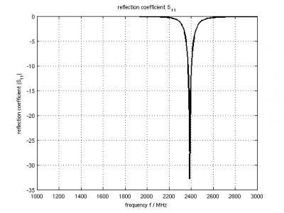
- Calculate & Plot S-Parameter and accepted power
% plot reflection coefficient S11
figure
plot( freq/1e6, 20*log10(abs(s11)), 'k-', 'Linewidth', 2 );
grid on
title( 'reflection coefficient S_{11}' );
xlabel( 'frequency f / MHz' );
ylabel( 'reflection coefficient |S_{11}|' );

drawnow
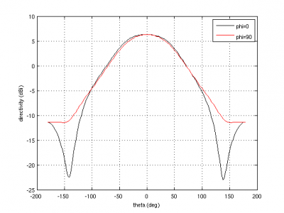
- Calculate & Plot antenna parameter & radiation pattern
%% NFFF contour plots %%%%%%%%%%%%%%%%%%%%%%%%%%%%%%%%%%%%%%%%%%%%%%%%%%%%
%find resonance frequency from s11
f_res_ind = find(s11==min(s11));
f_res = freq(f_res_ind);

% calculate the far field at phi=0 degrees and at phi=90 degrees
disp( 'calculating far field at phi=[0 90] deg...' );

nf2ff = CalcNF2FF(nf2ff, Sim_Path, f_res, [-180:2:180]*pi/180, [0 90]*pi/180);

% display power and directivity
disp( ['radiated power: Prad = ' num2str(nf2ff.Prad) ' Watt']);
disp( ['directivity: Dmax = ' num2str(nf2ff.Dmax) ' (' num2str(10*log10(nf2ff.Dmax)) ' dBi)'] );
disp( ['efficiency: nu_rad = ' num2str(100*nf2ff.Prad./real(P_in(f_res_ind))) ' %']);

% normalized directivity as polar plot
figure
polarFF(nf2ff,'xaxis','theta','param',[1 2],'normalize',1)

% log-scale directivity plot
figure
plotFFdB(nf2ff,'xaxis','theta','param',[1 2])
% conventional plot approach
% plot( nf2ff.theta*180/pi, 20*log10(nf2ff.E_norm{1}/max(nf2ff.E_norm{1}(:)))+10*log10(nf2ff.Dmax));

drawnow

%%
disp( 'calculating 3D far field pattern and dumping to vtk (use Paraview to visualize)...' );
thetaRange = (0:2:180);
phiRange = (0:2:360) - 180;
nf2ff = CalcNF2FF(nf2ff, Sim_Path, f_res, thetaRange*pi/180, phiRange*pi/180,'Verbose',1,'Outfile','3D_Pattern.h5');

figure
plotFF3D(nf2ff,'logscale',-20);


E_far_normalized = nf2ff.E_norm{1} / max(nf2ff.E_norm{1}(:)) * nf2ff.Dmax;
DumpFF2VTK([Sim_Path '/3D_Pattern.vtk'],E_far_normalized,thetaRange,phiRange,'scale',1e-3);
Results
Suggested Enhancements
- Use the one-third/two-third method to enhance thin-metal accuracy
- 3D radiation pattern plot (included in openEMS/matlab/examples/antennas/patch_antenna.m)
- create a patch array (included in openEMS/matlab/examples/antennas/patch_antenna_array.m)


